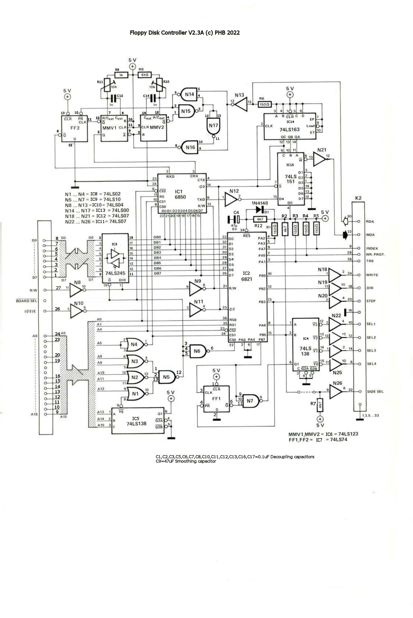
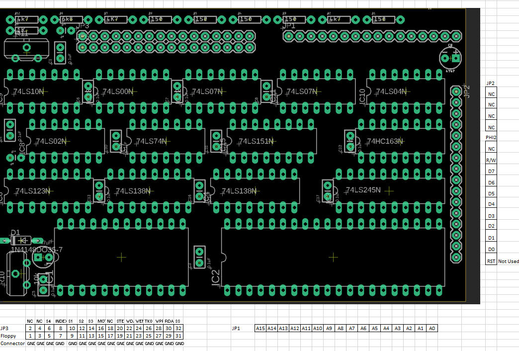
| NOTE I am now shipping a newer version of the PCB (ver 2.3A). Circuitry is identical to previous version except all Address, Data and Control signals are accessible at edge pins to match my 6502SBC PCB. See Layout here. | |||||||||||||||||||||||||||||||||||||||||||||||||||||||||||||||||||||||||||||||||||||||||||||||||||||||||||||||||||||||||||||||||||||||||||||||||||||||||||||||||||||||||||||||||||||||||||||||||||||||||||||||||||||||||||||||
| NOTE If you intend to use with genuine OSI Superboard or UK101 with any expansion already using the optional expansion socket via 8T88s, is advisable to connect address and data bus etc directly to the mainboard, DO NOT connect via 8T88s and expansion socket. The data bus is buffered on the PCB and address decoding is on board. There is no facility to manage the DD signal. | |||||||||||||||||||||||||||||||||||||||||||||||||||||||||||||||||||||||||||||||||||||||||||||||||||||||||||||||||||||||||||||||||||||||||||||||||||||||||||||||||||||||||||||||||||||||||||||||||||||||||||||||||||||||||||||||
What is it?This is a Printed Circuit board for a Floppy disk controller. It will interface 5.25 inch Single Side shugart type floppy disk drives to generic 6502 computers. It also supports Gotek Floppy emulators. It supports up to 4 disk drives and requires OSI65D3.1 or OSI65D3.3 operating system on floppy or as an .HFE USB file for a Gotek. They can be downloaded at http://osi.marks-lab.com/software/osios5.html or below. Why did you make it?I have a love of 6502 based systems from around 1979 when I built my first kit computer (UK101) and I expanded it by adding a floppy disk drive. I wanted to take a nostalgia trip and recreate my system using purpose built PCBs. I still had the original OS on disk which booted perfectly after approx 40years!! What makes it special?You cannot buy this interface elsewhere so I had to research and design a PCB I could use. |
|||||||||||||||||||||||||||||||||||||||||||||||||||||||||||||||||||||||||||||||||||||||||||||||||||||||||||||||||||||||||||||||||||||||||||||||||||||||||||||||||||||||||||||||||||||||||||||||||||||||||||||||||||||||||||||||
 |
|||||||||||||||||||||||||||||||||||||||||||||||||||||||||||||||||||||||||||||||||||||||||||||||||||||||||||||||||||||||||||||||||||||||||||||||||||||||||||||||||||||||||||||||||||||||||||||||||||||||||||||||||||||||||||||||
|
|||||||||||||||||||||||||||||||||||||||||||||||||||||||||||||||||||||||||||||||||||||||||||||||||||||||||||||||||||||||||||||||||||||||||||||||||||||||||||||||||||||||||||||||||||||||||||||||||||||||||||||||||||||||||||||||
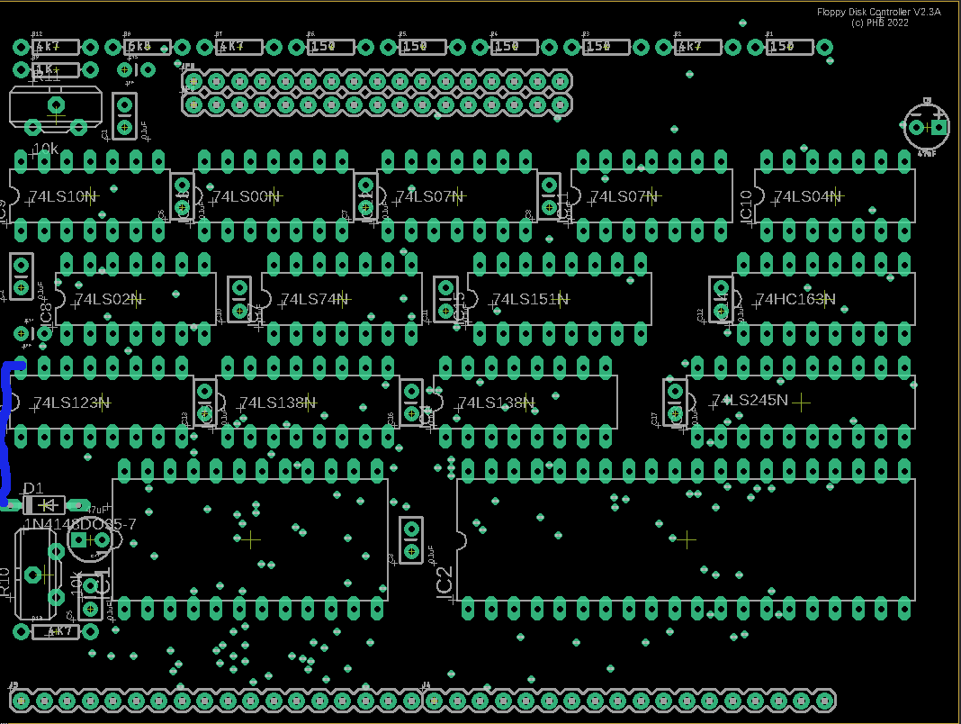
| Version 1 board layout. | |||||||||||||||||||||||||||||||||||||||||||||||||||||||||||||||||||||||||||||||||||||||||||||||||||||||||||||||||||||||||||||||||||||||||||||||||||||||||||||||||||||||||||||||||||||||||||||||||||||||||||||||||||||||||||||||
 |
|||||||||||||||||||||||||||||||||||||||||||||||||||||||||||||||||||||||||||||||||||||||||||||||||||||||||||||||||||||||||||||||||||||||||||||||||||||||||||||||||||||||||||||||||||||||||||||||||||||||||||||||||||||||||||||||
| Version 2.3A layout | |||||||||||||||||||||||||||||||||||||||||||||||||||||||||||||||||||||||||||||||||||||||||||||||||||||||||||||||||||||||||||||||||||||||||||||||||||||||||||||||||||||||||||||||||||||||||||||||||||||||||||||||||||||||||||||||
 |
|||||||||||||||||||||||||||||||||||||||||||||||||||||||||||||||||||||||||||||||||||||||||||||||||||||||||||||||||||||||||||||||||||||||||||||||||||||||||||||||||||||||||||||||||||||||||||||||||||||||||||||||||||||||||||||||
| Connector Pins are: | |||||||||||||||||||||||||||||||||||||||||||||||||||||||||||||||||||||||||||||||||||||||||||||||||||||||||||||||||||||||||||||||||||||||||||||||||||||||||||||||||||||||||||||||||||||||||||||||||||||||||||||||||||||||||||||||
| D7,D6,D5,D4,D3,D2,D1,D0,A15,A14,A13,A12,A11,A10,A9,A8,A7,A6,A5,A4,A3,A2,A1,A0,NC,PHI2,R/W,NC,NC,NC,NC,NC,GND,NC,NC,+5V | |||||||||||||||||||||||||||||||||||||||||||||||||||||||||||||||||||||||||||||||||||||||||||||||||||||||||||||||||||||||||||||||||||||||||||||||||||||||||||||||||||||||||||||||||||||||||||||||||||||||||||||||||||||||||||||||
| NOTE: On Early 2.3A boards a strap must be fitted between the cathode of D1 to pin 16 of the 74123 next to it. | |||||||||||||||||||||||||||||||||||||||||||||||||||||||||||||||||||||||||||||||||||||||||||||||||||||||||||||||||||||||||||||||||||||||||||||||||||||||||||||||||||||||||||||||||||||||||||||||||||||||||||||||||||||||||||||||
| Later 2.3A Boards do not require the strap. You can test by checking that D1 cathode to Pin 16 of 74123 is 0 ohms resistance. | |||||||||||||||||||||||||||||||||||||||||||||||||||||||||||||||||||||||||||||||||||||||||||||||||||||||||||||||||||||||||||||||||||||||||||||||||||||||||||||||||||||||||||||||||||||||||||||||||||||||||||||||||||||||||||||||
|
Because my SBC uses a
serial terminal for input/output, the OSI DOS versions are slightly
modified to use a relocated port. (The UK101/Superboard 2 have their
ACIAs at $F000, I chose to have mine at $8000 to make it easier for
address decoding.) In order for the Floppy Interface to work with my
6502 SBC, the 'bootloader' needs to be modified. It is easy to do if you
wish to do it yourself: With a genuine OS65D3.1 or 3.3 disk or image loaded, reset SBC and select 'D'. After disk activity has finished reset SBC and select 'M' Copy the address and data text from below: .2277/7F and paste to host or your comms programme's equivalent. You should then have A* as a prompt. |
|||||||||||||||||||||||||||||||||||||||||||||||||||||||||||||||||||||||||||||||||||||||||||||||||||||||||||||||||||||||||||||||||||||||||||||||||||||||||||||||||||||||||||||||||||||||||||||||||||||||||||||||||||||||||||||||
| Original OS65D3.1 Image for 5.25 Floppy can be downloaded here. | |||||||||||||||||||||||||||||||||||||||||||||||||||||||||||||||||||||||||||||||||||||||||||||||||||||||||||||||||||||||||||||||||||||||||||||||||||||||||||||||||||||||||||||||||||||||||||||||||||||||||||||||||||||||||||||||
| Original OS65D3.3 Image for 5.25 Floppy can be downloaded here. | |||||||||||||||||||||||||||||||||||||||||||||||||||||||||||||||||||||||||||||||||||||||||||||||||||||||||||||||||||||||||||||||||||||||||||||||||||||||||||||||||||||||||||||||||||||||||||||||||||||||||||||||||||||||||||||||
| Modified OS65D3.1 Image for Gotek can be downloaded here | |||||||||||||||||||||||||||||||||||||||||||||||||||||||||||||||||||||||||||||||||||||||||||||||||||||||||||||||||||||||||||||||||||||||||||||||||||||||||||||||||||||||||||||||||||||||||||||||||||||||||||||||||||||||||||||||
| Modified OS65D3.3 Image for Gotek can be downloaded here | |||||||||||||||||||||||||||||||||||||||||||||||||||||||||||||||||||||||||||||||||||||||||||||||||||||||||||||||||||||||||||||||||||||||||||||||||||||||||||||||||||||||||||||||||||||||||||||||||||||||||||||||||||||||||||||||
| OS65D3.3 Tutorial Disks for Gotek can be downloaded here 1,2,3,4 | |||||||||||||||||||||||||||||||||||||||||||||||||||||||||||||||||||||||||||||||||||||||||||||||||||||||||||||||||||||||||||||||||||||||||||||||||||||||||||||||||||||||||||||||||||||||||||||||||||||||||||||||||||||||||||||||
 |
|||||||||||||||||||||||||||||||||||||||||||||||||||||||||||||||||||||||||||||||||||||||||||||||||||||||||||||||||||||||||||||||||||||||||||||||||||||||||||||||||||||||||||||||||||||||||||||||||||||||||||||||||||||||||||||||
| (c) 2021,2022,2023 Paul Bartlett | |||||||||||||||||||||||||||||||||||||||||||||||||||||||||||||||||||||||||||||||||||||||||||||||||||||||||||||||||||||||||||||||||||||||||||||||||||||||||||||||||||||||||||||||||||||||||||||||||||||||||||||||||||||||||||||||
