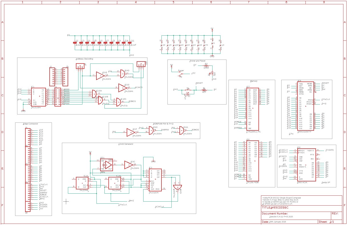
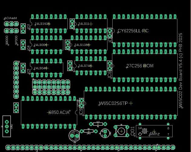
| It consists of a Printed Circuit Board with provision for 10 integrated circuits attached. I tend to use 'LS' varieties but I guess faster low current versions might do They are: | ||||||||
| W65C026TPG-14 Western Digital CMOS 6502 14Mhz Microprocessor. Or R65C02P | ||||||||
| MC6850 Motorola 6850 ACIA Asynchronous Communications Interface Adapter. | ||||||||
| NM27C256Q National Semiconductor 32k x 8 CMOS Eprom. | ||||||||
| HY62256B Hynix 32k x 8 CMOS Static Ram. | ||||||||
| SN74LS00 Quad 2 input NAND Gate. | ||||||||
| SN74LS11 Triple 3 input AND Gate. | ||||||||
| SN74LS14 Hex Schmitt Inverter. | ||||||||
| 74LS74 Dual D-Type Flip Flops. | ||||||||
| HD74LS138 1 of 8 Decoder. | ||||||||
| M74LS163 Synchronous 4 bit counter. | ||||||||
|
Each IC power is decoupled by 0.1uF capacitors.
|
||||||||
| The system clock is generated by a Crystal Oscillator and is further divided by the flip flops to give /2MHz and /4MHz feeds. The /4Mhz is fed to the CPU and is further divided by the 4 bit counter to give a suitable clock frequency for the ACIA to communicate. a 4Mhz clock at 19200 baud, an 8Mhz clock at 38400 baud. There is also provision for resetting the CPU with a micro button switch and resistor circuit. | ||||||||
|
The board has a power switch and led to indicate when powered up. Along the bottom edge of the board there is provision for a 36 way pin connector. This provides access to the system buses for modification or expansion. From the left to the right the pins are: D7 D6 D5 D4 D3 D2 D1 D0 A15 A14 A13 A12 A11 A10 A9 A8 A7 A6 A5 A4 A3 A2 A1 A0 CPUCLK PHI2 CPURW CPURESET RAMRW ROMOE ACIACLK /2MHZCLK Gnd RX TX 5v The system can be powered from a USB-Serial dongle and setting a comms program such as Putty, Hyperterminal or Teraterm to the dongle Com port at 19200-8-N-1 (4Mhz Clock) or 38400-8-N-1 (8Mhz Clock) with no handshaking will work. Pressing the reset button once connected should result in: CEGMON..... A/B/C/E/M/W? (or D/C/W/M if using the Monitor with Floppy Disk Bootstrap) on the terminal screen. NB: CAPS LOCK ON!! |
||||||||
| The Memory map is as follows:- | ||||||||
| $0000 - $7FFF 32K x 8 RAM | ||||||||
| $8000 - $87FF ACIA Control and Status registers | ||||||||
| $8800 - $8FFF Unused. | ||||||||
| $9000 - $FFFF Remainder of Eprom. | ||||||||
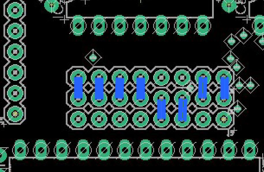
Alongside the ACIA there are jumper pins J1. Normally there
will be links from the centre row to the row next to the 74LS04 chip.
These are the address decoding links and refer to (l to r) :
| $8000-$8FFF. |
| $9000-$9FFF | $A000-$AFFF | $B000-$BFFF | $C000-$CFFF | $D000-$DFFF | $E000-$EFFF | $F000-$FFFF | When any link is placed from the centre row down toward the ACIA, that address decoding signal will be sent to the corresponding pin on the vertical row to the left of them. This allows you some flexibility with non-ram addressing. |
| The new Version 5.4 PCB has links top left which allow the ACIA to be addressed at $8000 (my software choice) or $F000 as per UK101/Superboard. | ||||||||
| I can supply an Eprom (I now charge an �5 GBP to cover the cost of the EPROM) with the following programs pre-loaded: | ||||||||
| $A000 - $BFFF Microsoft BASIC 1979 as was supplied with OSI Superboard and Compukit UK101. It has been modified to fix the Garbage Collection routine bug and doesn't prompt for 'Memory Size' as Ram is fixed at 32768 bytes cold start. | ||||||||
| $C000 - $D23F Spare. Set to $FF for future programming. (If using Floppy Disk, the I/F board is addressed here at $C000-$C003 for 6821 PIA and $C010-$C011 for 6850 ACIA) | ||||||||
| $D240 - $DFFF OSI 6502 Assembler. Modified to be in Eprom. | ||||||||
| $E000 - $E7FF OSI Extended Monitor is here. | ||||||||
| $E800 - $F7FF Spare. Set to $FF for future programming. | ||||||||
| $F800 - $FFFF Cegmon V2 Monitor. Heavily modified UK101/Superboard monitor to provide Terminal communications through the ACIA and a new menu structure to allow access to (A)ssembler,(B)Assembler Warm Start,(C)old Start Basic,(E)xtended Monitor,(M)onitor and (W)arm Start Basic. | ||||||||
| In the case of the Disk Bootstrap Version you have (D)isk,(C)old Start Basic,(W)arm Start Basic and (M)onitor. The Extended Monitor can still be accessed by switching in to (M)onitor and entering 'E000' then 'G'. The Assembler can still be accessed by switching in to (M)onitor and entering 'D240' then 'G' | ||||||||
| Credit must be given to Grant Searle who inspired my quest to build a 6502 based development board and supplied the Cegmon patches to utilise RS232 as opposed to a memory mapped screen. | ||||||||
| The software supplied is not being sold as I have no legal right to it. It is being included at no extra cost to the hardware in order for the board to be useable as supplied. UK101/Superboard Microsoft Basic, OSI Assembler Extended Monitor, and the Cegmon monitor are available from many sources on the internet either as Hex dumps or source code and there are many other variants of software available for a 6502 running similarly to this board. Experimentation is key. | ||||||||
| ROM Images can be downloaded below:= | ||||||||
| CEGMON..... A/B/C/E/M/W? | ||||||||
| CEGMON..... D/C/W/M? Includes Floppy Disk Bootstrap | ||||||||
 |
||||||||
 |
||||||||
| Clarification of switch connections. | ||||||||
 |
||||||||
| OSI Assembler and Extended Monitor Guide. | ||||||||
| UK101 Manual. | ||||||||
| CEGMON manual. | ||||||||
| NOTE: If using this SBC with the disk Interface addressed @ $C000 etc. Blue links above should be set as below: | ||||||||
 |
||||||||
 |