| What is it? | |||
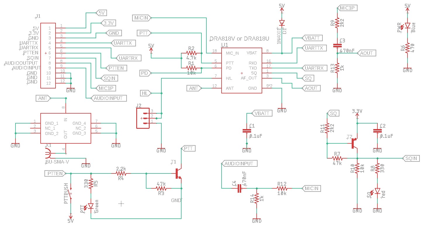
| This is a breakout Printed Circuit Board for a SA818 transceiver module. | |||
| Why did you make it? | |||
| I am a licensed Radio Amateur and building electronics is part and parcel of the culture. I have wanted to construct a radio using this module for some time and successfully built the shield for an OrangePi zero published by VoltNode. A great design but designed exclusively for the OrangePi. I wanted to be able to interface any MCU to make programming the module easier, hence the PCB here. If you are interested in purchasing this PCB, please visit my Tindie store. | |||
| . | |||
| What makes it special? | |||
|
It is a very simple low cost design, that can be controlled by RaspberryPis, Arduinos and Pico's etc. |
|||
 |
|||
| This is an updated version of the Version 1 PCB which allows provision of a PTT Button and better connection labelling. | |||
 |
|||
|
Connections are: |
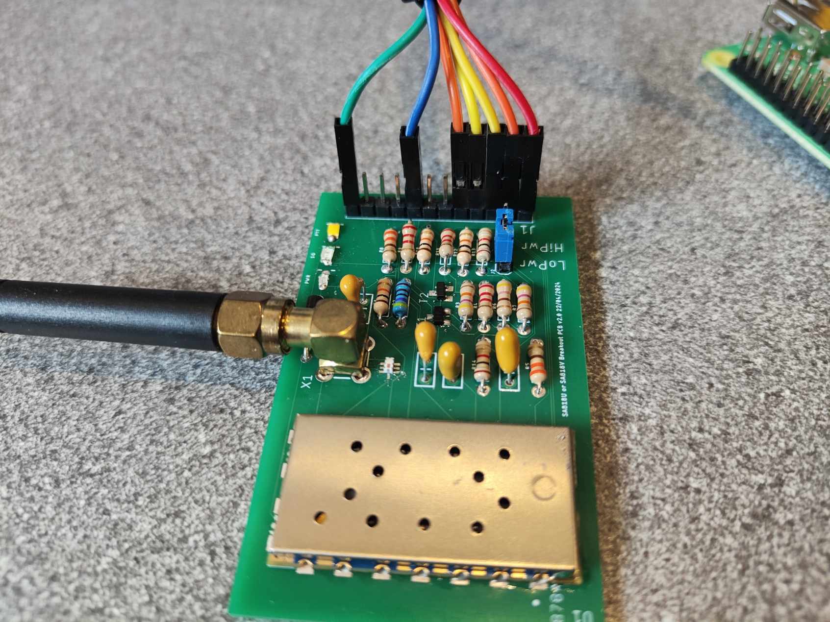
The below image shows a populated PCB with an SA818V module. |
||
 |
|||
|
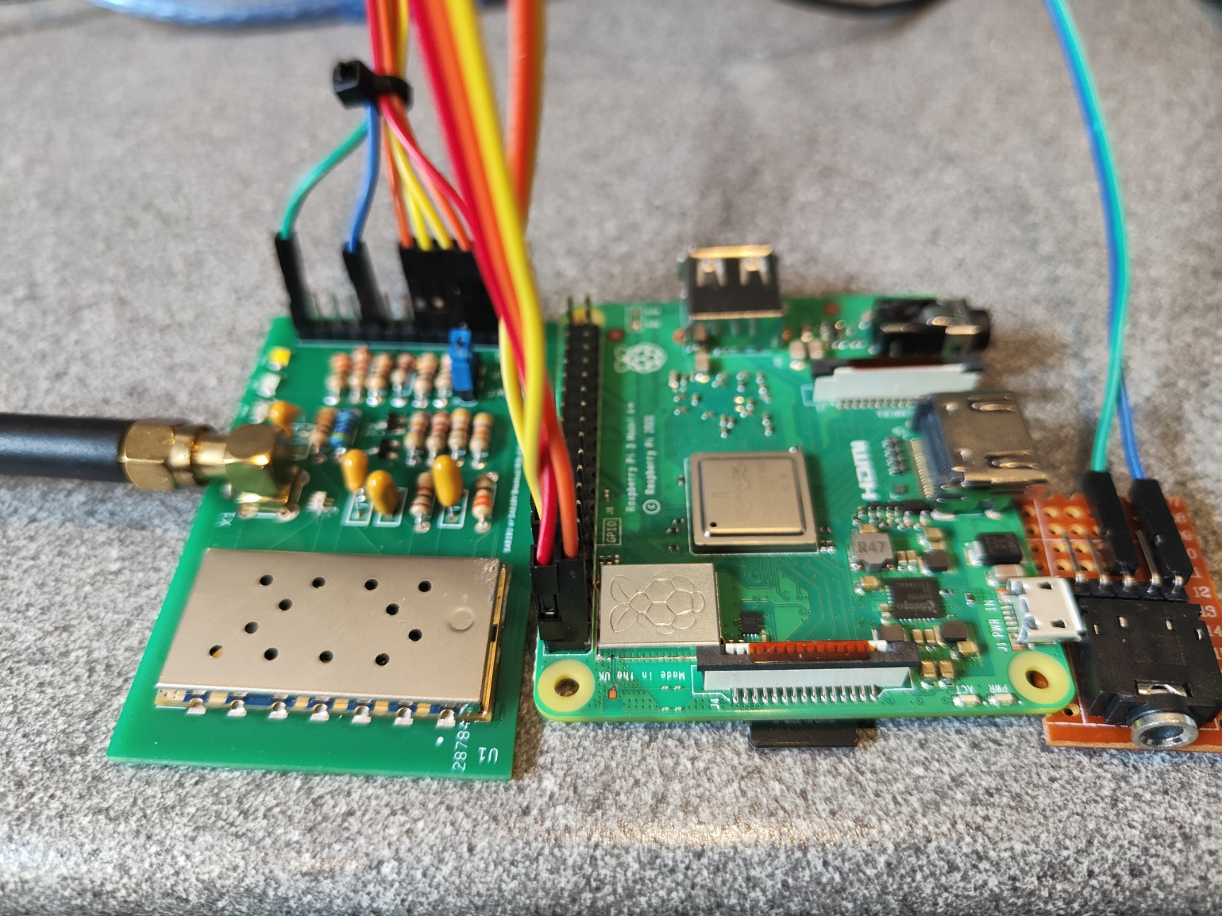
The below image shows a PCB connected to a Pi 3 A+ and with an audio out socket. |
|||
 |
|||
|
Parts needed are: |
|||
 |
|||
| (c) 2021,2022,2023,2024,2025,2026 Paul Bartlett | |||